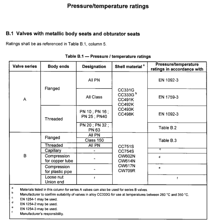
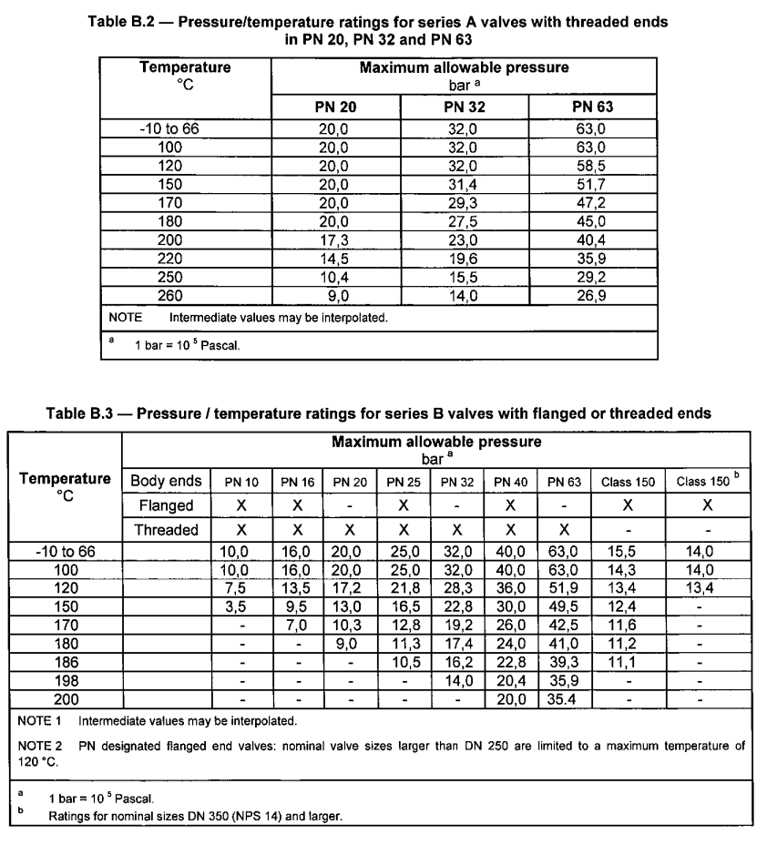
A. Pressure – Temperature rating
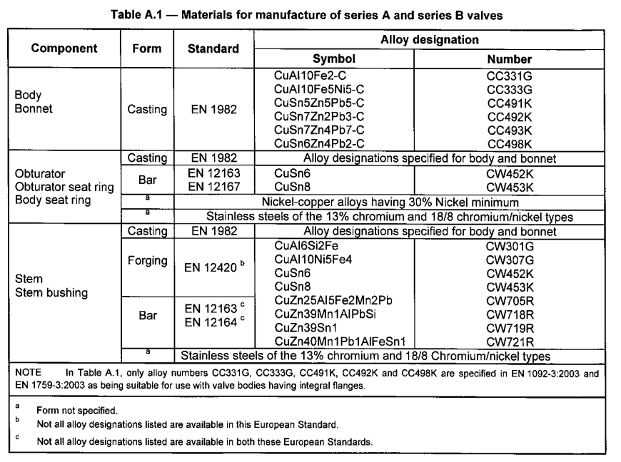
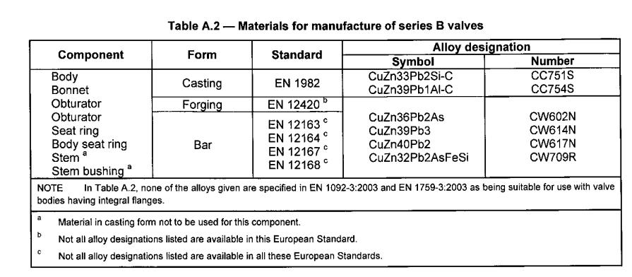
B. Material covered under BS EN 12288
A. Pressure – Temperature rating
B. Material covered under BS EN 12288
Any water fitting, which when installed, will carry or receive water from the public mains water supply in the UK, must comply with the Water Supply (Water Fittings) Regulations or Scottish Byelaws. These require that a water fitting should not cause waste, misuse, undue consumption or contamination of the water supply and must be ‘of an appropriate quality and standard’.
WRAS Approval is the easiest way to demonstrate compliance as it is granted directly by representatives of the water suppliers and is therefore accepted by every water supplier in the UK.
WRAS Product Approval: Whole products such as valves, boilers & showers undergo mechanical and water quality testing. This type of approval demonstrates full compliance with requirements of the regulations and byelaws, provided the fitting is installed according to any conditions given with the approval.
WRAS Material Approval: Non-metallic materials & components, such as rubber sheet material & ‘O’ rings, undergo testing only for their effects on water quality. This type of approval demonstrates that the non-metallic material/component does not itself contaminate the water and therefore satisfies this particular requirement of regulations and byelaws.
Where do the regulations apply?
The Regulations are typically in effect between the boundary of a property and the point of discharge as illustrated below.
Source: WRAS What is a WRAS Approval?
Source2 : WIKI
Unless the code governing what you do dis-allows it, or the requirement is for seamless pipe only, the two are interchangeable.
As an example, the company I work for is a distributor of steel pipe, flanges and fittings. When we order pipe of this type, we order it “quad stencilled”, which means it complies with and is certified to all of the following:
A/SA 53B
A/SA106B
API5L B
CSA Z245.1 Grade 290 cat I
Because these standards are so similar, it is easy to make one piece of pipe that will satisfy the requirements of all. It is far more efficient for us to do this than carry seperate inventories of each A53B, A106B, API 5L B and CSA.
A couple of notes to go with this.
A106-B pipe is, be definition, seamless, whereas, A53-B, API 5L -B and CSA can be either seamless OR welded. So, when we order quad stencilled pipe, is has to be seamless. Also, the spec for CSA is higher than for the ASTM/ASME and API grades, but CSA is a requirement for a number of our customers, which is why we add that on.
Duplex stainless steels are becoming more common. They are being offered by all the major stainless steel mills for a number of reasons:
- Higher strength leading to weight saving
- Greater corrosion resistance particularly stress corrosion cracking
- Better price stability
- Lower price
There is a conference on the subject of duplex every 2-3 years where dozens of highly technical papers are presented. There is a lot of marketing activity surrounding these grades. New grades are being announced frequently.
Yet, even with all this interest, the best estimates for global market share for duplex are between 1 and 3%. The purpose of this article is to provide a straightforward guide to this steel type. The advantages and disadvantages will be described.
Principle of Duplex Stainless Steels
The idea of duplex stainless steels dates back to the 1920s with the first cast being made at Avesta in Sweden in 1930. However, it is only in the last 30 years that duplex steels have begun to “take off” in a significant way. This is mainly due to advances in steelmaking techniques particularly with respect to control of nitrogen content.
The standard austenitic steels like 304 (1.4301) and ferritic steels like 430 are relatively easy to make and to fabricate. As their names imply, they consist mainly of one phase, austenite or ferrite. Although these types are fine for a wide range of applications, there are some important technical weaknesses in both types:
Austenitic – low strength (200 MPa 0.2% PS in solution annealed condition), low resistance to stress corrosion cracking
Ferritic – low strength (a bit higher than austenitic, 250 MPa 0.2% PS), poor weldability in thick sections, poor low temperature toughness
In addition, the high nickel content of the austenitic types leads to price volatility which is unwelcome to many end users.
The basic idea of duplex is to produce a chemical composition that leads to an approximately equal mixture of ferrite and austenite. This balance of phases provides the following:
- Higher strength – The range of 0.2% PS for the current duplex grades is from 400 – 550 MPa. This can lead to reduced section thicknesses and therefore to reduced weight. This advantage is particularly significant for applications such as:
o Pressure Vessels and Storage Tanks
o Structural Applications e.g. bridges- Good weldability in thick sections – Not as straightforward as austenitics but much better than ferritics.
- Good toughness – Much better than ferritics particularly at low temperature, typically down to minus 50 deg C, stretching to minus 80 deg C.
- Resistance to stress corrosion cracking – Standard austenitic steels are particularly prone to this type of corrosion. The kind of applications where this advantage is important include:
o Hot water tanks
o Brewing tanks
o Process plant
o Swimming pool structuresHow the Austenite/Ferrite Balance is Achieved
To understand how duplex steels work, first compare the composition of two familiar steels austenitic 304 (1.4301) and ferritic 430 (1.4016).
Structure Grade EN Number C Si Mn P S N Cr Ni Mo Ferritic 430 1.4016 0.08 1.00 1.00 0.040 0.015 – 16.0/18.0 – – Austenitic 304 1.4301 0.07 1.00 2.00 0.045 0.015 0.11 17.5/19.5 8.0/10.5 – The important elements in stainless steels can be classified into ferritisers and austenitisers. Each element favours one structure or the other:
Ferritisers – Cr (chromium), Si (silicon), Mo (molybdenum), W (tungsten), Ti (titanium), Nb (niobium)
Austenitisers – C (carbon), Ni (nickel), Mn (manganese), N (nitrogen), Cu (copper)
Grade 430 has a predominance of ferritisers and so is ferritic in structure. Grade 304 becomes austenitic mainly through the use of about 8% nickel. To arrive at a duplex structure with about 50% of each phase, there has to be a balance between the austenitisers and the ferritisers. This explains why the nickel content of duplex steels is generally lower than for austenitics.
Here are some typical compositions of duplex stainless steels:
Grade EN No/UNS Type Approx Composition
Cr Ni Mo N Mn W Cu 2101 LDX 1.4162/
S32101Lean 21.5 1.5 0.3 0.22 5 – – DX2202 1.4062/ S32202 Lean 23 2.5 0.3 0.2 1.5 – – RDN 903 1.4482/
S32001Lean 20 1.8 0.2 0.11 4.2 – – 2304 1.4362/
S32304Lean 23 4.8 0.3 0.10 – – – 2205 1.4462/
S31803/
S32205Standard 22 5.7 3.1 0.17 – – – 2507 1.4410/
S32750Super 25 7 4 0.27 – – – Zeron 100 1.4501/
S32760Super 25 7 3.2 0.25 – 0.7 0.7 Ferrinox
255/
Uranus 2507Cu1.4507/
S32520/
S32550Super 25 6.5 3.5 0.25 – – 1.5 In some of the recently developed grades, nitrogen and manganese are used together to bring the nickel content to very low levels. This has a beneficial effect on price stability.
At present, we are still very much in the development phase of duplex steels. Therefore, each mill is promoting its own particular brand. It is generally agreed that there are too many grades. However, this is likely to continue until the “winners” emerge.
Corrosion Resistance of Duplex Steels
The range of duplex steels allows them to be matched for corrosion resistance with the austenitic and ferritic steel grades. There is no single measure of corrosion resistance. However, it is convenient to use the Pitting Resistance Equivalent Number (PREN) as a means of ranking the grades.
PREN = %Cr + 3.3 x %Mo + 16 x %N
The following table shows how the duplex steels compare with some austenitic and ferritic grades.
Grade EN No/UNS Type Typical PREN 430 1.4016/
S43000Ferritic 18 304 1.4301/
S30400Austenitic 19 441 1.4509/
S43932Ferritic 19 RDN 903 1.4482/
S32001Duplex 22 316 1.4401/
S31600Austenitic 24 444 1.4521/
S44400Ferritic 24
316L 2.5 Mo 1.4435 Austenitic 26 2101 LDX 1.4162/
S32101Duplex 26 2304 1.4362/
S32304Duplex 26 DX2202 1.4062/ S32202 Duplex 27
904L 1.4539/
N08904Austenitic 34 2205 1.4462/
S31803/
S32205Duplex 35 Zeron 100 1.4501/
S32760Duplex 41 Ferrinox 255/
Uranus 2507Cu1.4507/
S32520/
S32550Duplex 41 2507 1.4410/
S32750Duplex 43 6% Mo 1.4547/
S31254Austenitic 44 It must be emphasised that this table is only a guide to material selection. It is always important to assess the suitability of a particular with a full knowledge of the corrosive environment.
Stress Corrosion Cracking (SCC)
SCC is a form of corrosion which occurs with a particular combination of factors:
- Tensile stress
- Corrosive environment
- Sufficiently high temperature. Normally 50 deg C but can occur at lower temperatures around 25 deg C in specific environments, notably swimming pools.
Unfortunately, the standard austenitic steels like 304 (1.4301) and 316 (1.4401) are the most susceptible to SCC. The following materials are much less prone to SCC:
- Ferritic stainless steels
- Duplex stainless steels
- High nickel austenitic stainless steels
The resistance to SCC makes duplex steels suitable materials for many processes which operate at higher temperatures, notably:
- Hot water boilers
- Brewing tanks
- Desalination
Stainless steel structures in swimming pools are known to be prone to SCC. The use of standard austenitic stainless steels like 304 and 316 is forbidden in this application. The best steels to use for this purpose are the high nickel austenitic steels such as the 6% Mo grades. However, in some cases, duplex steels such as 2205 (1.4462) and the superduplex grades can be considered.
Barriers to Using Duplex Steels
The attractive combination of high strength, wide range of corrosion resistance, moderate weldability would seem to offer great potential for increasing the market share of duplex stainless steels. However, it is important to understand the limitations of duplex stainless steels and why they are always likely to be “niche players”.
The advantage of high strength immediately becomes a disadvantage when considering formability and machinability. The high strength also comes with lower ductility than austenitic grades. Therefore, any application requiring a high degree of formability, for example, a sink, is ruled out for duplex grades. Even when the ductility is adequate, higher forces are required to form the material, for example in tube bending. There is one exception to the normal rule of poorer machinability, grade 1.4162.
The metallurgy of duplex stainless steels is much more complex than for austenitic or ferritic steels. This is why 3 day conferences can be devoted just to duplex! This factor means that they are more difficult to produce at the mill and to fabricate.In addition to ferrite and austenite, duplex steels can also form a number of unwanted phases if the steel is not given the correct processing, notably in heat treatment. Two of the most important phases are illustrated in the diagram below:
Sigma phase 475 degree embrittlement Both of these phases lead to embrittlement, i.e. loss of impact toughness.
The formation of sigma phase is most likely to occur when the cooling rate during manufacture or welding is not fast enough. The more highly alloyed the steel, the higher the probability of sigma phase formation. Therefore, superduplex steels are most prone to this problem.
475 degree embrittlement is due to the formation of a phase called α′ (alpha prime). Although the worst temperature is 475 deg C, it can still form at temperatures as low as 300 deg C. This leads to a limitation on the maximum service temperature for duplex steels. This restriction reduces the potential range of applications even further.
At the other end of the scale, there is a restriction on the low temperature use of duplex stainless steels compared to austenitic grades. Unlike austenitic steels duplex steels exhibit a ductile-brittle transition in the impact test. A typical test temperature is minus 46 deg C for offshore oil and gas applications. Minus 80 deg C is the lowest temperature that is normally encountered for duplex steels.
Going Further with Duplex Stainless Steels
More detailed information on duplex can be found in:Practical Guidelines for the Fabrication of Duplex Stainless Steels
Summary of Duplex Characteristics
- Twice design strength of austenitic and ferritic stainless steels
- Wide range of corrosion resistance to match application
- Good toughness down to minus 80 deg C but not genuine cryogenic applications
- Particular resistance to stress corrosion cracking
- Weldable with care in thick sections
- More difficult to form and machine than austenitics
- Restricted to 300 deg C maximum
Source: Article: Duplex Stainless Steels – A Simplified Guide
Static electricity is experienced during seasons when the air is dry. The crackle sound that occurs when removing a sweater is from the static electricity generated by friction between clothing materials. Similarly, the slight pain sensation experienced when touching a door knob after walking on carpet is due to the static electricity, which was built up in the body from rubbing the carpet, being discharged across the small gap between the door knob and your hand.
Such experiences with static electricity can be relatively common occurrences, so we often don’t pay much attention to them in our daily lives.However, static electricity can be a big problem for electronic parts. At a few kilovolts, our bodies only experience a slight pain sensation (assuming a very slight current level), but some electronic parts can be ruined by only 0.1 kV.
Countermeasures for static electricity are included in the analytical instruments themselves, but larger amounts of static electricity could cause them to malfunction.Furthermore, some laboratory instruments, such as HPLC (high performance liquid chromatograph) systems, which use flammable organic solvents, require being especially careful due to the risk of fire.
In addition, because it is difficult to understand the mechanism of how static electricity accidents occur, and because some aspects that lead to static electricity accidents only occur when several factors coincide, caution is often ignored. Nevertheless, particular caution is especially required when using large amounts of solvent, because if an accident does occur, it can cause a great deal of damage.This page specifically describes HPLC effluents flowing into liquid waste containers, but the danger also applies to non-HPLC situations where a solvent with low conductivity flows into a container with low conductivity.
• The Possibility of Accidents from Static Electricity Generated by Flowing Liquid
Static electricity generated near the HPLC outflow into a liquid waste container could potentially cause an accident. The process is described below.
1. Generation of Static Electricity
When liquid is passed through thin tubing at a high flowrate, as it is in HPLC systems, the electrostatic charge of the flowing matter generates static electricity (flow electrification). (The charge level is higher for poorly conductive solvents flowing through plastic tubes. In addition, large amounts of air bubbles flowing through the tube can amplify the static electricity.A: Charge that moves along with liquid flow
B: Charge that is fixed to a solid surface and cannot move
Generation of Static Electricity by a Liquid Flowing over a Solid
2. Accumulation of Static Electric Charge
If electrostatically charged liquid accumulates in an electrically insulated container, the amount of charge gradually increases to a point where it can easily generate high voltages, on the order of several kV.3. Release of Energy Through Electrical Discharge
If an electrical conductor comes within a certain distance of the container, an electrical discharge occurs, which releases thermal energy.4. Ignition of Flammable Substances
If there is a sufficient concentration of flammable gas in the surrounding atmosphere, the gas is more easily ignited.Figure 2 illustrates potential accident situations.
Situations with Danger of a Static Electricity Accident
Intake of Air Bubbles Increases Static Electricity
• Preventing Static-Electricity Accidents
To prevent static electricity accidents, measures should focus on preventing the generation and accumulation of static electricity. In addition, to further ensure that accidents are prevented, it is important to implement multiple prevention measures simultaneously. In particular, the following measures should be taken if large amounts of flammable solvents are used.
Measure 1
Use a metal liquid waste container (with a conductive interior surface, such as a plated metal can) and connect the container to ground.
Properly ground liquid waste containers. There is no point in using a metal container if it is not grounded or the ground wire becomes disconnected. (P/N 228-21353-91 can also be used as a ground wire.) This ensures that static charge does not accumulate in the waste liquid or the container.
Even some metal containers have surfaces that are oxide-coated or laminated and, therefore, may not be conductive. Use an electrical tester to confirm that the container is grounded. If only liquid with a very low conductivity (10-10 S/m or less) is discharged into the waste container, one method is to add a safe conductive liquid to the container.
Configuration with Measures to Prevent Static Electricity Implemented
Measure 2
To prevent sparks from entering the waste container, keep the size of any gaps at inlet and outlet openings as small as possible.
(To minimize such gaps, P/N 228-21354-91 caps can also be used for 18 L and 4 L cans.)Measure 3
Keep electrostatically charged objects, including human bodies, away from the waste container.
To prevent the body from becoming charged, wear anti-static clothing or shoes, ground the body using an anti-static wrist strap (with a 1 MΩ resistor to protect the body), or provide conductive floor surfaces in work areas, such as with anti-static floor mats. If you have not taken any anti-static measures, touch a grounded metal object before approaching the waste container in order to ground any electrostatic charge from your body.Measure 4
Use tubing with a larger inner diameter (at least 2 mm, for example) for drain lines through which large amounts of liquid flow.
Air bubbles in the liquid can increase electrostatic charge by a factor of several tens. Check the tubing connections for air leaks.Measure 5
If the liquid waste container cannot be made conductive, make sure the end of the drain tube remains below the surface of the liquid in the waste container. Alternatively, place grounded metal in the liquid.
However, this method is mostly ineffective for liquids with low conductivity (10-10 S/m or less).Measure 6
Use a liquid waste container that is as small as possible to minimize the damage in the event of a fire.Measure 7
Increasing the humidity level (above 65 %, for example) can have an anti-static effect. Therefore, do not let the room become dry.Static electricity accidents can be prevented by observing the measures indicated above. These measures may seem like an unnecessary bother, but being prepared for such possibilities is also important.
As a manufacturer of HPLC systems, we hope to supply easy-to-use peripheral products that are carefully designed for safety as well.
Additional Remarks There are many other areas of the laboratory, besides the HPLC system, that require particular caution regarding static electricity.
1.Flammables: Laboratories contain many flammable substances, such as organic solvents. Keep flammable substances covered to prevent exposure. Provide ventilation for flammable vapors. (Select the height of ventilation fans based on most solvents being heavier than air, but hydrogen being lighter than air).
2.Electrical System: Circuit boards are especially vulnerable to static electricity. In particular, if a statically charged person touches an electrical device with a metal tool, it can cause a malfunction or an instantaneous power interruption. Form a habit of touching the building or water pipes to eliminate any static charge before touching an electrical device.
3.Powders: Powders can cling or jump about due to static from friction with the container or from taking on the static charge from humans. When weighing powders, an ionizer can be used to eliminate static electricity.
Source: Beware of Static Electricity Generated by Flowing Liquids : SHIMADZU (Shimadzu Corporation)
Stellite alloys are a group or a range of cobalt-chromium alloys. They are designed to be resistant to wear and corrosion. These alloys may also have some portions of tungsten or molybdenum and some small but critical amounts of carbon. Stellite is a trademarked name of Deloro Stellite Company supplying Stellite alloys like Stellite3, Stellite 6, Stellite 12 and Stellite 21. Deloro Stellite Company also supplies other products like casting, machinery, welding, coating, knives and many others. The alloy was invented in the early 1900s by American metallurgist Elwood Haynes as a proper substitute for easily staining silverware.
The CAS Registry Number for Stellite alloys is 12638-07-2.
There are many types of Stellite alloys composed of varying quantities of cobalt, chromium, molybdenum, tungsten, iron, nickel, boron, aluminum, carbon, manganese, phosphorus, silicon, titanium and sulfur in different proportions. Most Stellite alloy compositions contain at least four to six of the listed elements.

Picture 1 – Stellite alloy
Stellite alloys do not have any specific chemical formula as various types of alloys are formed by combining a number of elements in different proportions. The various types of Stellite alloys are represented by using numbers, such as Stellite 1, Stellite 6K and Stellite 706.
A special form of Stellite known as Talonite is manufactured by hot-rolling and hardening a specific alloy combination. Talonite combines the properties of hardness, machinability and wear resistance. It is important to note that not all types of Stellite alloys can be processed to create Talonite.
Stellite alloys are non-magnetic alloys which are highly resistant to corrosion. A range of different alloy compositions are prepared by combining different elements in varying proportions and the properties of an individual alloy composition might vary from an alloy of a different composition. Different alloy compositions are used for different purposes and valued for their functional flexibility. The alloy Stellite 100 is mostly used nowadays for cutting tools as it is very hard and is capable of maintaining a great cutting edge even when exposed to high temperatures. The alloy is also resistant to processes such as hardening and annealing that might result from excessive heat. Other Stellite alloys are manufactured to combine the properties of corrosion resistance, wear resistance and the ability to tolerate extreme temperatures.
Stellite alloys can be characterized as having great hardness and toughness. They are also normally highly resistant to corrosion. The extreme harness of these alloys frequently makes it difficult to work with them and so anything made from these alloys are normally very expensive. Usually, Stellite parts are precisely cast to avoid any need of further excessive machining. Stellite alloys are more frequently machined by grinding instead of cutting. These alloys usually have very high melting points resulting from the combined content of cobalt and chromium.
The various uses of Stellite alloys are discussed below:
Stellite alloys are normally very stable materials. However, they can react with oxidizing agents and mineral acids to form explosive hydrogen gas which can cause fire hazards.
Under normal circumstances, handling of Stellite alloys hardly poses any risk of health hazards. However, machining or welding with these alloys can produce dust, fumes and small particles of component alloy elements. These particles can pose a serious threat to human health when they enter the body in excess of maximum exposure limits.
Inhalation: Inhaling particles of Stellite alloy generated from grinding, welding or similar processes can cause asthma and metal flume fever. Component materials like boron, chromium, cobalt, copper, manganese, molybdenum, nickel and vanadium are respiratory irritants.
Ingestion: Stellite particles normally do not enter the human body through ingestion. However in some cases a person’s hands, clothing or foods and drinks can get contaminated with dusts from Stellite alloy materials and the particles may enter the body through activities such as smoking, eating, drinking and nail biting. Ingesting Stellite particles can cause vomiting, diarrhea, nausea and abdominal pain.
Skin: Irritation, sensitization or allergic dermatitis can occur from the some of the components of Stellite alloys. When the skin comes in contact with vanadium, copper and nickel, it may result in dermatitis. Exposure of the skin to cobalt might cause allergic skin reactions and dermatitis. Skin exposed to manganese might suffer from excessive sweating. Vanadium and boron exposure causes skin irritation.
Eyes: If the eyes get contaminated by coming in contact with soiled fingers or airborne particles, it might result in irritation or abrasion of the eyes. Particles of Stellite materials can cause irritation of the eyes resulting from mechanical abrasion. Severe allergic conjunctivitis and eye irritation might result when dusts of cobalt enter the eyes. Irritation may also be caused by dusts of copper.
Chronic health effects resulting from Stellite alloys are difficult to detect as these alloys are made up of several elements. Effects of chronic inhalation include pulmonary fibrosis, chronic obstructive lung disease, rhinitis and bronchitis. Chronic occupational exposure to dusts of cobalt results in goiter, bloody urine and polycythemia.
Some elements of Stellite alloys have been recognized as carcinogenic substances by The International Agency for Research on Cancer (IARC). Exposure to nickel and nickel compounds, cobalt and cobalt compounds and hexavalent chromium can greatly increase the risk of cancer among workers dealing with these alloys.
Individuals already having sensitivity to certain elements and are prone to develop allergic reactions to metals like nickel, copper, chrome and cobalt might possibly encounter dermatitis and skin rashes. Persons already suffering from impaired pulmonary function can develop airway diseases and health conditions such as emphysema, asthma and chronic bronchitis, etc. when excessive concentrations of alloy fumes or dusts are inhaled. If any of these health conditions are already present, the inhalation of Stellite alloy particles can aggravate the symptoms. If a person is already suffering from prior damages to the Circulatory, Neurologic (nervous), Renal (kidney) or Hematogic (blood) systems, proper examinations or screening should be conducted for appropriate diagnosis of these patients. They should also be prohibited from entering areas contaminated by dusts of Stellite alloys.
Ventilation: The area should be well ventilated to minimize contamination of dust, fume and particles. Air exposure of materials should be kept below the recommended limits of exposure.
Respiratory: If the room is not properly ventilated and the exposure levels of alloy dust is not maintained below the exposure limits, adequate respiratory protection needs to be used by the working personnel. The respirators should be NIOSH-approved and have a proper air purifying filter.
Skin: Rubber or leather gloves should be used while dealing with Stellite alloys to avoid skin contact and for preventing metal abrasions and cuts. Unnecessary and risky skin contact can be easily avoided by using protective coveralls.
Eye: Safety goggles or glasses should be worn while entering a contaminated area.
Inhalation: The victim suffering from breathing difficulty due to inhalation of dust particles and fumes should be removed to an area of fresh air. A physician needs to be consulted if the breathing still does not improve.
Ingestion: The victim should drink plenty of water and try to vomit. A doctor should be consulted for ensuring further safety.
Skin: The infected area should be washed nicely with plenty of water. The victim should take a shower if possible. Contaminated clothing should be removed. Medical attention is required if irritation of skin persists.
Eye: The eyes should be washed well with ample amounts of water. A doctor needs to be consulted if eye irritation persists. While working with powders and dusts of Stellite alloys, a person should not wear contact lenses.
Environmental Surveillance: Air samples should be taken from the industrial working area for regularly checking the levels of air contamination.
Medical Surveillance: The workers should regularly go through a thorough health check up. Tests like chest x-rays, lung tests and routine physical examinations should be conducted on regular intervals to ensure safety of the workers.
Waste Disposal: Wastes of Stellite alloys should be disposed of by following the relevant Local, Provincial and Federal regulations regarding waste management.
Stellite alloys should not be used in nuclear power plants as cobalt can be changed to Cobalt-60 in nuclear reactors, which is a harmful radioisotope having a half life of five years and releases strong gamma radiation.
Stellite alloys are often a first choice in many industrial applications and functions. They are highly valued for their high resistivity to corrosion and weariness and hardness.
| 1.0 Valve Design | |
| Design methodology, qualification and performance verification for production chokes is covered by the API specification 6A (ISO 10423) for surface equipment and API 17D for subsea equipment. These valves may be supplied with API, ASME or other (manufacturer specific) end connections. Valve ratings must specify pressure, temperature, material classification and capacity. These valves are typically pressure or flow restriction valves, therefore manufactured with reduced bores resulting in higher fluid velocity within the body bore. The higher velocity can have a dramatic effect on erosion and corrosion rates. Typically, the higher velocity within the valve requires special consideration be given to material selection since corrosion inhibitors may not be effective. Choke valves typically experience high velocity at the throttling mechanism; accordingly, the materials selected for the trim components must consider the service conditions. Applicable specifications will include API 6A, API 17D, ANSI B16.34, ANSI B16.5, ISA S75.01, ISA S75.02, ANSI/FCI 70-2, ASME IX and NACE MR 01 75 (ISO 15156) | |
| 1.1 | Valve design methodology shall conform to API 6A latest edition. |
| 1.2 | Valve performance verification shall conform to API 6A PR2 and/or API 17D as applicable. |
| 1.3 | Valve internals including trim components shall be held in position by the bonnet bolting. Valve designs that utilize threads to secure the seat to the body are not recommended. |
| 1.4 | Valve design shall incorporate means for galling prevention on all dynamic sealing components. Metal to metal contact between sliding or rotating sealing components shall be avoided. In the case of metal seals the stem surface shall be protected with a suitable Tungsten Carbide coating to prevent galling. |
| 1.5 | Valve selection and design shall consider both purchase (CAPEX) and operation (OPEX) costs. Designs which incorporate the stem with trim components as a single unit should be avoided. |
| 1.6 | Capacity “Cv” rating shall be tested per ISA S75.02. Test results shall be accurate to within 5% of published data. |
| 1.7 | Valve designs shall incorporate a sliding stem design. Designs that rotate stems within seals shall be avoided. |
| 1.8 | Long valve travel is preferred for applications which require good controllability. For actuated applications long valve travel is required. Valve designs shall consider serviceability. Valves should be field serviceable without special tools. |
| 1.9 | Valve designs shall consider serviceability. Valves should be field serviceable without special tools. |
| Top | |
| 2.0 Body Design | |
| Choke bodies can be either a right angle design or an inline orientation; inline typically referred to as control valves. The angle type orientation is preferred for severe service applications. This orientation will allow improved fluid management since the fluid exiting the trim will travel directly into the valve outlet. The valve model is typically associated with the valve trim size as assigned by the valve manufacturer and therefore should not be the governing factor in valve selection. Proper valve selection should be based on valve capacity “Cv” as tested per ISA S75.02 verses flow condition requirements as calculated by ISA S75.01 methodology. Valve models may be smaller than the end connections supplied. Example: a 4″ valve may be fitted with 6″ end connections. |
|
| 2.1 | Body outlet profile shall be free of steps or abrupt change in diameters. Outlet sleeves, if necessary, must be accommodated with smooth transitions. |
| 2.2 | Screw-in seat assemblies shall not be used. Wetted threads should be avoided where possible. |
| 2.3 | Welded end connections are acceptable provided material selection and weld design conform to sound Engineering practice. All weld procedures must be ASME IX qualified. All alloy steel welds shall be stress relieved after welding. |
| 2.4 | Design may utilize a Hammer Union Nut Bonnet or Bolted Bonnet connection provided the Bonnet connection does not require special tools for valve disassembly. |
| 2.5 | Valves supplied with rotary actuators must utilize bolted bonnet designs. |
| 2.6 | In erosive applications a right angle body design is the preferred configuration. |
| 2.7 | End connections bores shall match mating flange bores/schedule to prevent unnecessary protrusions within the transition. |
| 2.8 | In corrosive applications the selected body material should be suitable for operation without the assistance of corrosion inhibitors. Higher velocities may diminish the benefit of inhibitors in valve bodies. |
| 2.9 | Valve model/size selected shall consider the effect of velocity on erosion and corrosion control. |
| Top | |
| 3.0 Trim design | |
| Trim designs may be classified as needle and seat, disk, or cage designs. Important factors to consider in trim selection are controllability defined as the “turn down ratio”; pressure recovery factor defined as the “FL factor”; valve capacity defined as the “Cv.” | |
| 3.1 | Design shall incorporate cage type trim. Trim design can be cage with external sleeve or internal plug design. Erosive or high pressure applications shall utilize an external throttling sleeve. Internal plug designs are not recommended for erosive or high pressure drop applications. |
| 3.2 | Valve trim should be designed with equal percentage opening characteristics for improved controllability. Quick opening characteristics shall not be supplied for modulating service. |
| 3.3 | For erosive service the ports should be positioned on the valve axis to reduce turbulence around the cage. For non-erosive service multi-ported cages are acceptable. |
| 3.4 | The shut-off mechanism is to be segregated and upstream of throttling ports. The seating face shall be metal to metal. |
| 3.5 | Materials used for erosion protection shall be solid tungsten carbide for erosive conditions and hardened stainless steel for non-erosion applications. Stainless steel carriers are acceptable for the flow sleeve; however the entire turbulent area and high velocity zone shall be protected with hardened trim material. The Cage shall be of solid hardened trim material. Hard facing or overlay shall not be used. |
| 3.6 | Tungsten Carbide trim materials shall utilize composite binders considering both erosion and corrosion properties. Minimum hardness for the tungsten carbide shall be Ra 93. Binder constitutes shall be Nickel, Chromium and Cobalt at a minimum. |
| 3.7 | Multi-Stage trim designs shall utilize a throttling mechanism on each stage. Designs which throttle on the initial or final stage only are not acceptable. |
| 3.8 | Trim design shall consider the potential for plugging and the design shall incorporate suitable means for passing normal sand and proppant that may be present within the fluid media |
| 3.9 | Designs should consider life cycle costs. Designs which incorporate the trim components into the valve stem should be avoided. |
| 3.10 | Trim design shall be capable of Class V shutoff as defined by ANSI/FCI 70-2 |
| Top | |
| 4.0 Valve Actuation | |
| Valve actuation may incorporate a manual operator (hand wheel) or pneumatic, hydraulic or electric actuators. For remote modulating operation the actuator is typically fitted with a positioner that will accept an input signal (either 3-15 psi, 6-30 psi or 4-20mA) to position the valve respective to the input signal. Linear actuators can incorporate fail positions defined as “fail open”, “fail closed” or “fail last”. This action is typically achieved through a mechanical spring, however in the case of linear hydraulic actuators; this can be accomplished through incorporation of an accumulator. | |
| 4.1 | Typical positional accuracy for linear actuated valves shall be 2% of valve travel for pneumatic applications and 1% for hydraulic applications. |
| 4.2 | Typical positional accuracy for rotary actuated valves shall be 1% of valve travel. |
| 4.3 | The number of moving parts external to the valve and actuator shall be minimized. Exposed linkages shall be avoided where possible. |
| 4.4 | Actuation mounting shall consider service. Adequate provision shall be made for operator safety and environmental protection. |
| 4.5 | Where linear actuation is utilized the actuator design should be double acting. |
| 4.6 | Where modulating service is specified, actuators are to be fitted with positioners. |
| 4.7 | Actuators shall be sized to ensure proper valve operation at shut-off and flowing conditions. In the case of “fail open/close” operation the actuator shall operate the valve to the desired position against worst case conditions. |
| 4.8 | Electric and rotary actuators shall provide suitable means to “torque seat” to maintain Class V shut-off capabilities. |
Source : masterflo
The globe valves, unlike the gate valves, allow the fluid to be regulated or controlled at the same time that they isolate the line. They have a movable disk-type element and a stationary ring seat in a spherical body.
Their spherical body shape is divided in two halves, separated by an internal baffle. This has an opening that forms a seat onto a movable plug, also called disk, that can be screwed in to shut the valve.
Globe valves are used for applications that requires throttling and frequent operation. They are normally used as sampling valves, that are normally shut, except when liquid flows are taken, because since the baffle restricts flow, they are nor recommended where full, unobstructed flows are required.
Straight pattern globe valves are the most commonly used. They are also the ones with a smaller permissible pressure drop.
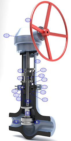 PARTS OF A STRAIGHT PATTERN GLOBE VALVE
1 Body
Available both in cast and forged steel, it has been designed to meet all the requirements of ASME, API and British Standards.
The body-bonnet connection is made by a pressure seal gasket. Its pre-stress condition is achieved by means of bolts screwed to the bonnet flange.
Ends are normally butt-welding although they can be also flanged on request.
All bodies are provided with integrally cast bosses, located and sized in accordance with ASME B16.34, which allow the provision of drain connections, supplied on request.
2 Bonnet
Usually constructed in the same materials as the body, being designed so that the wall thickness always exceeds the requirement of API 600.
A back seat (13) bush is fitted inside the bonnet lower cavity, to provide a closure when de valve is fully open. This permits the valve to be repacked while in service.
The bonnet has a deep stuffing box in which packing rings are placed.
Stuffing box is designed with sufficient space to allow lantern ring to be fitted.
3 Yoke
Separate rigid yoke is provided to withstand the thrust of the actuator. Large windows allow easy access and ventilation of the packing area. The yoke is connected to the body by a two pieces clamping ring (193) and four clamp bolts. This connection is very solid and enables easy maintenance at site.
The upper part of the yoke is suitably machined to house the yoke sleeve (11).
The yoke is usually made of cast carbon steel regardless the type of body material, unless otherwise required by the client.
4 Stem
Constructed in stainless steel, machined from solid bar stock. The single piece non rotating stem is connected to the disc (8) by a rounded head connection trough bearing ring (31A), and a stem retainer (29) and disc nut (18) assure the integrity of the kit.
A conical shoulder is also provided to ensure effective and tight seal backseat which allows the stuffing box to be replaced with the valve in service. The stem dimensions conform to API 600. Special care is taken in the machining of the stem, including the final polishing of the travelling area (contact with the stuffing box). This allows a low-friction surface and a superior corrosion resistance.
5-125 Gland bushing and flange
They are supplied in two separate self aligning pieces, to ensure uniform pressure is effected during tightening of the packing.
The upper part of the gland, which comes in contact with the gland flange, is spherical in shape.
The gland flange is made of carbon steel but, upon request, other materials can be supplied.
22-128 Gland bolts and nuts
The gland studs are of the eye-bolt type, which can be provided with live load systems, by means of belleville rings.
6 Seat ring
Supplied in forged stainless steel, hardfaced with Stellite-6 (2 mm of minimun thickness). Seat ring is renewable, normally welded to the body.
Sealing contact surface is lapped for a perfect tight seal. Contolled hardness differentials are maintained between the disc and the seat ring, as required by API 600 Std.
11 Yoke sleeve
Designed to permit removal from the bonnet or yoke while the valve is in service.
The yoke bushing assembly is mounted in ball bearings. It is normally made of cast aluminium bronze, having high resistance to wear and high melting point. Other materials such as Ni-resist can be supplied on request.
13 Back seat
The back seat can be supplied as a threaded stainless steel bush, welded to the bonnet or of integral type. It can be hardfaced with Stellite-6 or orther materials as required.
This seat allows the valve to be repacked under pressure.
15 Hand wheel
The handwheel is normally supplied of Hammer type, made of cast construction.
The handwheel is designed to allow easy operation of the valve. Other types of control are available and, in some cases, are indispensable for a good operation, for instance:
17 Pressure seal gasket
The pressure seal gaskets are usually supplied of compressed graphite, bordered on the upper and lower edges with braided filaments of carbon fiber and inconel wire.
Gaskets can also be made in stainless steel.
68 Packing
Packing is made of an adequate number of preformed rings.
For general applicatios high grade graphite material is supplied, using compressed rings in the center and braided anti-extrusion rings on top and bottom. Graphite is selected of an approved quality.
Other types of packing are also available for particular services.
132 Spacer ring
Made of a single piece covering the upper part of the pressure seal gasket. It is normally manufactured in the same material as the body.
133 Gasket retainer
It is made normally of the same material as the body, and constructed in four pieces, called segments. The segments are sized to minimize the gap among them.
The segmental ring supports all the forces transmitted from the bonnet through the pressure seal gasket and the spacer ring. It is calculated to withstand all the force without cracking.
134 Bonnet retainer
Designed sufficiently resistant to withstand the forces transmitted by the bonnet screws (111).
The bonnet retainer is normally made of same material as the body, but it can be constructed in any other material on request. It is machined to match exactly with the body, what guarantees a pefect alignment of the unit.
193 Yoke clamp
The body-yoke connection is created by means of a bipartite clamping ring. The internal connection between the clamp, body and yoke is conical, assuring a perfect tightening.
8 Disc
Constructed in forged stainless steel.
Disc is of swivel type, allowed to turn round freely upon the stem. Normally is of loose, Plug type, though can also of Ball, Needle and Parabolic shapes (equal percentage). Contact face is overlayed with Stellite-6 (2 mm of minimun thickness).
The stem-disc combination can be adapted to Stop-Check function.
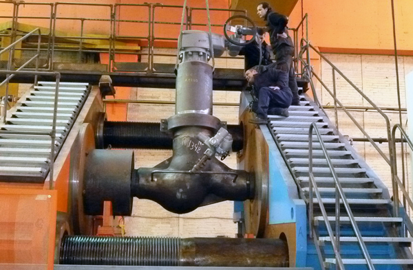
Straight pattern globe valve being tested
STANDARD MATERIALS

OTHER MATERIALS
Other materials are available on request. The trim (•) components are:
Source: Babcock Globe Valve
[B] BLOW-OUT PROOF STEM: A retaining ring is installed between the machined stem groove and gland retainer step.
[C] ADJUSTABLE STEM PACKING: The stem packing system features easy access to adjusting hex head nuts without requiring removal of the actuator. The system consists of a gland ring, a gland retainer, studs, hex head nuts and lock washers. A 1/4 turn of the hex head nuts is usually all that is required should field adjustment ever be needed. Both hex head nuts must be evenly adjusted and not overtightened.

[D] STEM SEAL: The stem seal system provides constant compression for a positive seal around the stem. PTFE packing seals the stem and a carbon fiber anti–extrusion ring contains the packing. Flexible graphite rings are available for high temperature applications and are standard on fire safe valves.
[E] STEM BEARINGS: Top and bottom bearings, consisting of a 316 Stainless Steel shell with a TFE/glass fabric liner bearing surface securely support the stem. The stem bearings provide excellent resistance to corrosion and distortion from high temperatures and mechanical loading forces.
[F] TAPER PINS: Taper pins are precision fit into reamed holes.
[G] DISC: The disc has been engineered to maximize flow and minimize resistance providing a high Cv. Stainless Steel is standard.
[H] INTERNAL TRAVEL STOP: Designed to prevent travel of the disc and minimizing possible seat damage, therefore extending the service life of the seat.
[I] RESILIENT SEAT: Energizer encapsulated in RTFE
[J] FULL-FACED SEAT RETAINER: Retainer is firmly attached by bolts located outside of sealing area, protecting the bolts from corrosion.
[K] BODY: All body styles offer bi-directional sealing as standard to full ASME Class 150, 300 or 600 ratings. Extended neck allows for 2″ of pipeline insulation and easy access to stem packing adjustments and actuator mounting
Source: High Performance Butterfly Valve – Bray/McCannalok: Double Offset Series 40/41


