Valves

Abbreviations and Terminology:
FC: Fail closed
FL : Fail locked
FO : Fail open
MOV: Motor Operated Valve
PRV : Pressure Relief Valve
PSV : Pressure Safety Valve
SOV : Solenoid Operated Valve

Armature: Part of an electric machine that strengthens magnetic fields.
Bonnet: Removable cover giving access to valve trim.
Cast: Method of producing shaped components by pouring molten material into a mould.
De-energised: Having no electric current passing through it.
Dynamic seal: A seal between parts that move relative to each other.
Energised: Having electric current passing through it.
Erosion: A slow wearing away, usually by a fluid flowing over a surface.
Fail closed: Describing a valve that automatically closes when the system fails.
Fail open: Describing a valve that automatically opens when the system fails.
Fail safe: Describing something that goes to a safe condition when the system fails.
Flow rate: Volume of fluid flowing past a point in unit time; SI units litres/sec.
Forged: Method of producing components by hammering hot metal into shape, usually between shaped dies.
Gear Ratio: The ratio between diameters or numbers of teeth on meshing gears.
Overpressure: Pressure that is higher than the specified value.
Perimeter: The distance all around the outside of an area.
Pig (pigging): A plug that is pushed through a pipeline by a gas or liquid to performvarious functions such as flushing, inspection and cleaning.
Port: An entry or exit through which fluids pass.
Regulating valve: Another name for a throttling or flow-control valve.
Setpoint: pressure A predetermined pressure value at which a component is set tooperate.
Turbulence: Flow that is not smooth or regular.
Yoke: External part of a valve that supports stem bushing.

Valves control the flow of fluids through pipes by:

• Starting and stopping flow—to control process or isolate part of a pipeline
• Changing the flow rate—allowing more or less fluid to flow
• Re-directing flow from one line to another at a pipeline
junction
• Allowing flow in one direction only
• Reducing fluid pressure
• Keeping the pressure in a container or pipeline below a fixed maximum
• Preventing accidents by relieving overpressure in a container or pipeline.

It is very important to use the correct:

• Valve type—to suit the task it performs, as described above
• Size—to suit the pipe size and the flow rate required
• Material—to suit the fluid passing through it and to avoid corrosion.

Basic Valve Components:

The design of different types of valves and some of the components used may vary. There are, however, some basic parts that are common to most valves. These parts are shown in Figure.

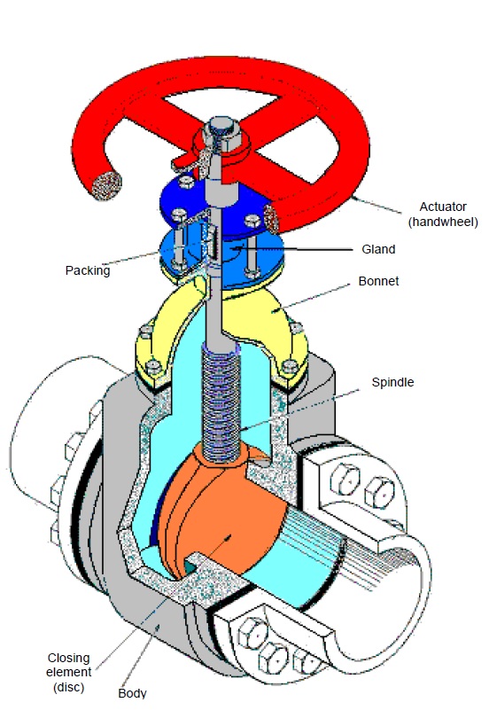
The valve body is the main part of the valve. All other parts fit onto the body. It is usually cast or forged and the shape varies with the type of valve. Inlet and outlet pipes fit onto the valve body through threaded, bolted (flanged) or welded joints. The fluid passes through the valve body when the valve is open. The valve body must be strong enough to take the maximum pressure of the process fluid. It must also be made of a material that is not attacked by the fluid.

The valve bonnet is a removable cover fitted to the body. Some bonnets support themoving parts of the valve. Others just close the hole in the body through which themoving parts pass for assembly and dismantling.

The valve trim is the name give to the parts inside a valve. This normally includes:
• The opening/closing element—closes the fluid path through the valve body
• The valve stem—connects the actuator to the closing element
• The valve seat—makes a seal with the closing element when the valve is closed
• Sleeves—sometimes used to guide the stem

Valve packing was described in detail in the earlier module in this course: Gland Packing. It allows the valve stem to pass into the valve body without loss of fluid or fluid pressure from the valve. It forms a dynamic seal between the valve stem and the bonnet.

The actuator operates the stem and closing element assembly. The simplest actuator is the manually operated handwheel shown in the Figure . Other actuators may be operated by:

• Electric motor—motor operated valve (MOV)
• Electric solenoid—solenoid operated valve (SOV)
• Air—pneumatically operated valve
• Oil—hydraulically operated valve

Valves can be divided into four classes:

• Block valves—stop and start flow
• Throttle valves—control flow rate
• Non-return (or check) valves—prevent flow reversal
• Pressure control valves—prevent fluid pressure exceeding a set maximum.

Block Valves:

Block valves either allow full flow or stop flow completely. They should only be operated in the fully open or fully closed position. If they are only partly opened, they offer a lot of resistance to flow. Fluid friction and turbulence cause a loss of pressure in the fluid and can cause vibration.
Block valves are not meant to control flow rate.

There are four main types of block valve used on the plant:
• Gate valves
• Slide valves
• Ball valves
• Plug valves

Gate Valves:

They are used to start or stop a flow completely. They should not be used to control flow rate. Using a gate valve in a partially open position can damage the valve. Fluid flow across the gate causes erosion to the gate making it impossible to seal well against its seat.
Fluid can flow through most gate valves in either direction.
The closing element in a gate valve is a wedge-shaped disc or gate attached to the end of the stem, as shown in Figure. The gate fits into a wedge-shaped seat in the valve body to stop flow through the valve, as shown in Figure.

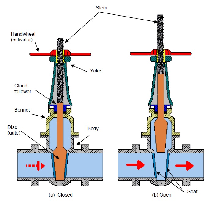
Turning the handwheel raises and lowers the gate. When the gate valve is fully closed, the gate fills the passage and stops the flow through the valve completely.
When the valve is fully opened, the gate is positioned above the passage in the valve body. This allows full flow through the valve, with little or no obstruction. There is very little pressure drop across the valve.
Gate valves are classed as linear-motion valves as the closing element moves in a straight line (e.g. down and up) to close and open the valve.
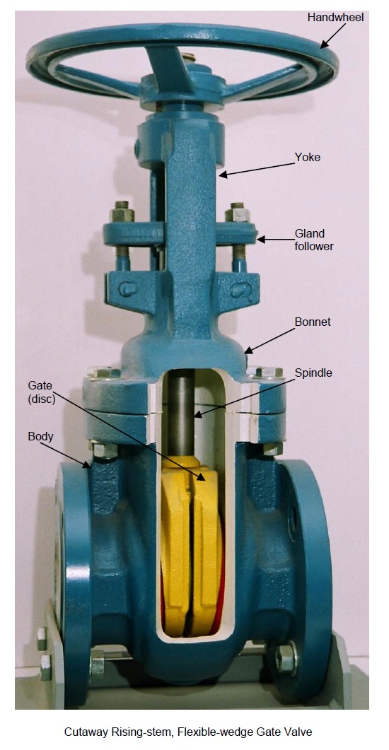
Gate valves can have rising or non-rising stems. The valve shown in Figure  has a rising stem. The stem moves up and down with the gate. A rising stem is fixed to the gate and can not turn in it. The upper part of the stem is threaded and screws into a mating thread in a bushing. The bushing is held in a yoke located at the top of the
bonnet as shown in Figure . The actuator turns the bushing in the yoke, screwing the stem into or out of the valve body.

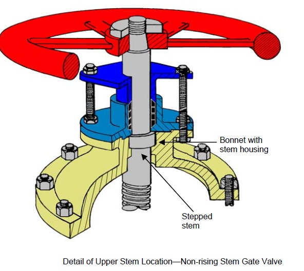
Non-rising stems are threaded at the bottom. This thread mates with a thread in the gate as shown in Figure . Left-hand threads allow clockwise rotation of the handwheel to lower the gate and close the valve.

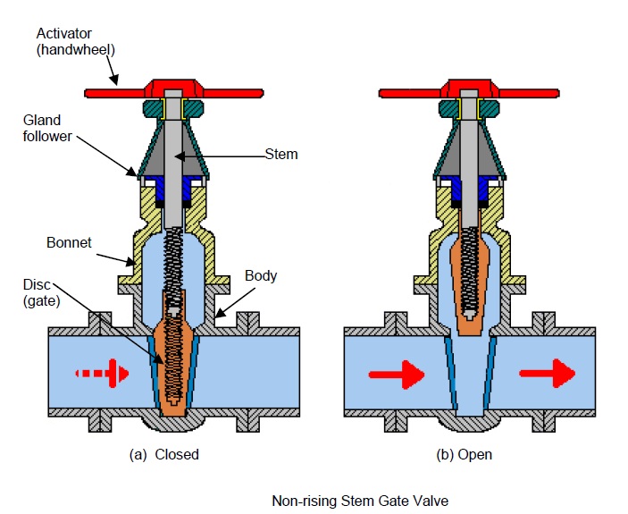
The stem is fixed to the actuator and turns with it, as shown in Figure . The stem can rotate in its housing but does not move axially.

An open gate valve allows anything that can pass through the pipeline to pass through the valve. Sometimes it is necessary to send solid objects along a pipeline. The object sent is called a pig and the process is called pigging. A pipeline is pigged to flush pipes, clear blockages or for inspection purposes. Gate valves allow these operations.

The gate, or disc design may be:

• Solid wedge
• Flexible wedge
• Split wedge
• Parallel disc

Most gate valves have solid-wedge discs.

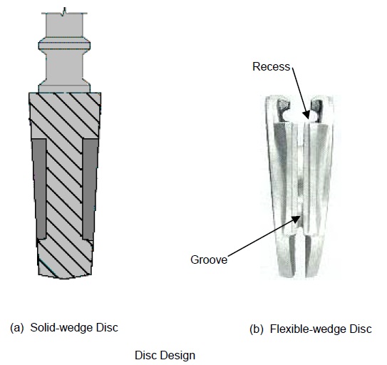
This is the simplest and strongest type of disc.

The flexible-wedge is also made in one piece. It has a groove cut around its perimeter that allows it to bend a little to fit the shape of the seat more easily. These discs may also have recesses cast into them to increase flexibility.

Flexible-wedge discs are used for valves in steam lines. When the temperature of a closed valve rises, solid-wedge discs can expand and stick in their seats. Flexible wedge discs can compress mere easily and are less likely to distort.
Figure 7  shows a rising-stem, flexible-wedge gate valve.

Figure 7

Split-wedge discs are made in two separate halves. This allows the wedge angle between their outer faces to adjust to fit the seat. This is especially useful if a solid particle is stuck between the disc and its seat. Split-wedge discs are used for gases,especially corrosive gases.
Parallel slide valves also have split discs. Their faces are parallel, not wedge shaped,as shown in Figure 8. A spring between the disc halves pushes them against theirseats. When the valve is closed, the disc on the outlet side is also pushed against its seat by the fluid pressure on the inlet side.


Figure 8

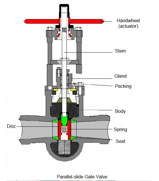
As the valve opens and closes, the sliding action keeps the disc faces clean but causeswear to discs and seats. When fully open, the discs are completely clear of the bore giving no obstruction to flow through the valve.

Gate valve seats may be integral with the valve body or separate seat rings. Integral seats are cut into the valve body and are part of the body. These seats can not be replaced. They can be repaired by lapping with grinding paste. Seat rings may be pressed or screwed into the body. These can be of a different material and can be replaced when worn or damaged.

Knife gate valves, have a simple, one-piece closing element. It is a parallel-sided plate that may move clear of the flow path to open or may have a hole that moves into the flow path.
These two types are shown in Figure 9(a) and (b).

Ball Valves
Ball valves start and stop flow by rotating a ball-shaped closing element. They are classed as rotational-motion valves. The ball has a hole through it of the same diameter as the pipeline. The valve is open when the hole lines up with the inlet and outlet of the valve body. Figure 10 shows a ball valve with part of the body cut away to show the closing element.
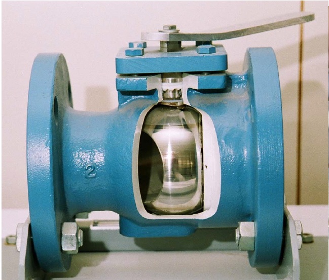
Cutaway Ball Valve

Figure 10
The valve above is shown partially open to show the hole in the ball. This is not thenormal valve position; a ball valve is normally only used in the fully closed or fully open positions.

Figure 11 shows the same ball valve looking through the valve inlet. In Figure11(a) the valve is in the closed position. In Figure 11(b) the valve is in the open position.

Figure 11

The open valve leaves a clear path for flow with no obstruction. These valves can bepigged.

The valve shown has a lever actuator that turns through 90o between the fully closed and fully open positions. The lever is in line with the pipeline when the valve is open.

To Be Continued…..

Plug Valves

Operation of a plug valve is similar to the ball valve; they are also rotational-motionvalves. The main difference is the shape of the closing element, which is a tapered plug of circular section. The plug has a hole called a port. Figure 12 shows a plug valve that is lined with PTFE to protect it from corrosion and allow lubricant-free operation.


Figure 12

Single-port plug valves are used to start and stop flow. Multi-port plug valves redirectflow from one pipeline to another. Figure 13 shows an example of a multiport plug valve.


Figure 13

 Flow Control (Throttle) Valves:

The control of flow rate by reducing the area of the flow path through a valve is calledthrottling. Throttling a fluid also reduces its pressure.

Block valves should not be used to throttle flow. The pressure drop across them is toogreat and the flow becomes turbulent. Fluid flow can be either smooth (laminar), or not smooth (turbulent) as shown in Figure

Fluid Flow Patterns

Turbulent flow can cause many problems in pipelines and equipment. In a valve, it can erode the closing element and valve seat. Erosion was described in the earlier module in this course: Bearings. It is the slow wearing away of a solid material by a fluid passing over it. Turbulent flow increases the rate of wear. Figure  shows smooth and turbulent flow in rivers.

Water Flow in Rivers
Throttle valves are designed to operate partially opened with little pressure loss and
turbulence. Throttle valves are also called regulating valves.
There are four main types:
• Globe valves
• Butterfly valves
• Diaphragm valves
• Needle valves
Globe Valves:
Globe valves are linear-motion valves and can look very similar to gate valves from the outside. Globe valves have rising stems but, unlike gate valves, the actuator is fixed to the stem and rises with it. Figure shows a globe valve in the fully closed
and open positions.
Figure :Globe Valve
Globe valve design makes them good for flow regulation as well as starting and stopping flow. In most designs, the flow direction is as shown in Figure. Here, the fluid pressure helps to push the valve open. The packing is not under pressure
when the valve is closed and this helps it to last longer.
 Figure : Flow through Z-type Globe Valve
The flow direction is often marked on the valve body. Make sure that you fit the valve the correct way around.
Globe valves can have three main types of body.
• Z-type
• angle
• Y-type
The valves shown in Figures above have Z-type bodies. The name is given because of the path the fluid has to take as it passes through the valve. It changes direction twice, like the letter Z.
Z-type globe valves are used mainly for small-size, low-pressure applications. In large, high-pressure lines, the changes of flow direction cause a large pressure drop and turbulence that can damage the trim.
Figure below shows an angle-type globe valve. The flow changes direction only once and the pressure drop is less than for the Z-type. It can be used for medium-pressureapplications.
Figure: Angle-type Globe Valve
Figure below shows a Y-type globe valve. Having the seat at about 45o to the flowdirection straightens the flow path and reduces the pressure drop. This type of valve can be used for high-pressure applications.
Figure:Y-type Globe Valve

Most globe valves use one of three types of disc:

• Ball
• Plug
• Composition

Ball discs have a curved lower surface. They seal on a tapered seat that has a flat
surface, as shown in Figure below. They are used mainly for low-pressure and low temperature applications.

Globe Valve Discs
Plug discs come in different shapes but are all tapered. The seat has a matching taper as shown in Figure (b).
Composition discs have a hard backing piece with a soft face as shown in Figure(c). Hard particles trapped between the disc and the seat push into the soft face, maintaining a good seal. Composition discs are replaceable.
Butterfly Valves:
Butterfly valves are rotational-motion valves. Like ball and plug valves, they need only a quarter turn (90o) to fully open or close them. They can start, stop and regulate flow, although they are not very good at completely stopping flow. Figure below shows a typical butterfly valve. The lever is in line with the pipeline when the valve is open.
Lever-operated Butterfly Valve
The closing element is a circular disc of a similar diameter to the ID of the pipe. The disc turns to open and close the valve. The disc or seat may be made of a polymer (plastic) to give a better seal.
Butterfly valves are simple and take up little space. This makes them especially good for use in large pipelines or where there is not much space. Operating a butterfly valve can take a lot of force as you have to push it against the fluid pressure. Larger valves usually have geared actuators to make operation easier, as shown in Figure below.

Source: Engineering Photos,Videos and Articels (Engineering Search Engine): Valves

Source: Wermac.com

Source: Wiki


Maximum Allowable Stem Torque (MAST) for Valve

It is maximum allowable torque a stem of a quarter turn valve can be subjected to without mechanical failure. Engineering unit Nm OR lb-in

During valve operation, torque delivered by actuator (Pneumatic or electric) at any stage, should not exceed MAST value. If it happens stem may be subjected to mechanical failure.

In some projects it has happened that MAST value calculated by valve vendor was higher than actual, even than it resulted in failure of stem.


follow main source

Source: Maximum Allowable Stem Torque (MAST)

Source: MAST Calculation


Piping Engineer Interview Questions

Below link is given for source of data, If you any issue please contact


  • What are the steps in selection of valve?
    What to handle, liquid, gas or powder, fluid nature, function, construction material, disc type, stem
    type, how to operate, bonnet type, body ends, delivery time, cost, warranty.
  1. What are functions of valves?
    Isolation, regulation, nonreturn
    and special purposes.
  2. What are isolating valves?
    Gate, ball, plug, piston, diaphragm, butterfly, pinch
  3. What are regulation valves?
    Globe, needle, butterfly, diaphragm, piston, pinch.
  4. What are nonreturn valves?
    6. What are special valves?
    multiport,
    flush bottom, float, foot, pressure relief, breather.
  5. What materials are used for construction of valves?
    Cast iron, bronze, gun metal, carbon steel, stainless steel, alloy carbon steel, polypropylene and other plastics, special alloys.
  6. What is trim?

Trim is composed of stem, seat surfaces, back seat bushing and other small internal parts that normally contact the surface fluid.

  1. Which standard specifies trim numbers for valve ?
    API 600.
  2. What are wetted parts of valve?
    All parts that come in contact with surface fluid are called wetted parts.
  3. What is wire drawing?
    This term is used to indicate the premature erosion of the valve seat caused by excessive velocity between seat and seat disc, when valve is not closed tightly.
  4. What is straight through valve?
    Valve in which the closing operation of valve is achieved by 90 degrees turn of the closing element.
  5. What pressure tests are carried out on valves?
    Shellhydrostatic,
    seathydrostatic,
    seatpneumatic
  6. What are available valve operators?
    Handlever, handwheel, chain operator, gear operator, powered operator likes electric motor,
    solenoid, pneumatic and hydraulic operators, Quick acting operators for nonrotary
    valves (handle lift).
  7. What are two types of ball valve?
    Full port design and regular port design, according to type of seat, soft seat and metal seat.
    16. What are ball valve body types?
    Single piece, double piece, three piece, the short pattern, long pattern, sand witch and flush bottom design.
  8. Why ball valves are normally flanged?
    Because of soft seat PTFE which can damage during welding.
  9. What are butterfly valve types?
    Double flange type, wafer lug type and wafer type.
  10. What are types of check valve?
    Lift check valves and swing check valves.
  11. What are nonslam
    check valves?
    Swing check valve, conventional check valve, wafer check valve, tilting disc check valve, piston check
    valve, stop check valve, ball check valve.
  12. Where stop check valve is used ?
    In stem generation by multiple boilers, where a valve is inserted between each boiler and the main


Source: Piping Design Engineer Interview Questions (Part-1) | Oil And Gas Club


Flange Thickness  Calculation

flange thickness calculation can be done by different methods like :

A. If you intend to use standard flanges, and by knowing the design conditions (pressure and temp.) of piping system and type of piping material:

In this case no calculations are required to find the flange dimensions, only go to ASME B16.5 and select the rating of flanges (like as 150#, 300#, … etc.) to suit the design conditions. Just by finding the flange rating (class), you can find all standard dimensions from tables of ASME B16.5, B16.47 or MSS SP44.

B. If you intend to use nonstandard flanges, As per ASME B31.3 Section 304.5.2 , These may be different shape. End blind.

The minimum thickness, considering the manufacturer ’s minus tolerance, shall be not less than tm

To calculate t, the rules of Section VIII, Division 1, UG-34 may be used

The minimum required thickness of flat unstayed circular heads, covers and blind flanges attached by bolts causing an edge moment in which case the thickness shall be calculated by the following formula:

When using Formula (2), the thickness t shall be calculated for both operating conditions and gasketseating, and the greater of the two values shall be used.

For operating conditions, the value of P shall be the design pressure, and the values of S at the design temperature and W from Formula (3) of 2-5(e) shall be used. For gasket seating, P equals zero, and the values of S at atmospheric temperature and W from Formula (4) of 2- 5(e) shall be used.

Where,

C = a factor depending upon the method of attachment of head, shell dimensions, and other items as listed in (d) below, dimensionless. The factors for welded covers also include a factor of 0.667which effectively increases the allowable stress for such constructions to 1.5S. (in our case C= 0.3)

d = diameter, or short span, measured as indicated in Fig. UG-34.

E = joint efficiency, from Table UW-12, of any Category A weld as defined in UW-3(a)(1).

hG = gasket moment arm, equal to the radial distance from the center line of the bolts to the line of the gasket reaction, as shown in Table 2-5.2.

P = internal design pressure (see UG-21).

S = maximum allowable stress value in tension from applicable table of stress values referenced by UG-23.

W = total bolt load given for circular heads for Formulas (3) and (4), 2-5(e) in UG-34 of ASME BPVC VIII Dev.1.


Ball Valve

Design acc.to API 6D, DIN3357Face-to-Face acc. to ASME B16.10Flange acc. to ASME B16.5, DIN EN1092Butt Weld acc. to ASME B16.25Test acc. to API 598, DIN3230Fire Proof acc. to API607Anti-H2S acc. to NACE MR-0175Size from 2” to 42”,Pressure from 150LB to 2500LB,PN16 to PN320We cover the following range of exotic alloys for our valve body and trims:Duplex and Super Duplex grades: 318LN, A182 F51, A182 F55, A479 F51, A995 4A, A995 Gr. 5A, A995 Gr. 6A, A890 Gr. 4A, A890Gr. 5A CEMN, A890Gr. 6A CD3MWCUN, A479 F55, UNS S31803, UNS S32205, UNS S32750, UNS S32760, X2CrNiMoN22-5-3, X2CrNiMoCuWN25.7.4, 1.4410, 1.4501, 1.4507, 1.4462, Ferralium 255, Uranus 45N®, Uranus 52N®.Titanium grades: Titanium Gr.2, Titanium Gr.3, Titanium Gr.5, T40, T60, TA6V, Ti6Al4V, UNS R50400, UNS R50550, UNS R56400, 3.7034, 3.7035, 3.7164, 3.7165, A182 316Ti.Zirconium – Zr: Zr 702, Zr 705, UNS R60702, UNS R60705.Uranus B6 grades: 904L, UNS N08904, 1.4539, X1NiCrMoCuN25-20-5, Uranus B6®.Tantalum – Ta grades: Ta, Ta pur ( 99.85 % min), Ta-2, 5%W (KBI 6) ;Ta-10%W (KBI 10).Nickel grades: Nickel 200, Nickel 201, UNS N02200, UNS N02200, 2.4060, 2.4061, 2.4066, 2.4068.Hastelloy® grades: HASTELLOY® B-2 alloy, HASTELLOY® B-3 alloy, HASTELLOY® C-22 alloy, HASTELLOY® C-276 alloy, HASTELLOY® C-4 alloy, UNS N10665, UNS N10675, UNS N06022, UNS N10276, UNS N06455, 2.4617, 2.4600, 2.4602, 2.4819, 2.4610, A494 CW12MW.Inconel and Incoloy grades: INCONEL® 600, INCONEL® 601, INCONEL® 617, INCONEL® 625, INCONEL® 718, INCONEL® 725, Inconel A494-CY40, INCOLOY® 800, INCOLOY® 800H, 800HT, UNS N06600, UNS N06601, UNS N06617, UNS N06625, UNS N07718, UNS N07725, UNS N08810, UNS N08811, 2.4816, 2.4851, 2.4663, 2.4856, 2.4668, 1.4876, 1.4958, 1.4959.Monel grades: MONEL® 400, MONEL® K500, UNS N04400, UNS NO5500, 2.4360, 2.4361, 2.4375.Alloy 20 grades: Alloy 20, Carpenter 20, A351 CN7M, A20 UNS 08020.High temperature and other exotic alloys: A182 F5, A182 F22, A216 WC6, A216 WC9, A182 F61, A182 F91, A182 F321, A182 F347, A182 F347H, A182 F44, 254 SMO, 6moly, 6mo, Avesta 904L, A217 C5, A182 F11, A351 CG8M, Aluminium Bronze Valve.Features:1.Blow-out proof stemFor the purpose of preventing the stem from flying off  resulting in abnormal rising of the inner pressure of valve,shoulder is fixed at the lower part of the stem.In addition,in order to prevent leakage resulting from burnout of packing set of the stem in a fire,thrust bearing is set at the contact position of the shoulder at lower part of the stem and valve body.Thus an inverse seal seat is formed which will prevent leakage and avoid accident.2.Key lockLocks can be used to lock the manual valve when  it is fully open or closed so as to prevent non-working personnel from pulling the handle which may result in misoperation of valve.It can also avoid opening or closing of valve resulting from the shock from pipelines or unpredictable factors that may cause an accident.For working pipelines such as combustible and explosive oil,gas and chemical medium,or for field piping site,the locking mechanism is especially useful.3.Anti-fire safe designWhen the trunnion ball valve be used normally,its sealed by seat and ball surface,seat retainer sealed by O-ring and body,this is soft sealed and reliable sealing.When the seat and O-ring are burnt,the seat retainer and body will be sealed by expanded graphite.Thus act anti-fire safe purpose. 4.Anti-static deviceIn order to prevent friction among ball,stem and PTFE that generates static electricity which may light the combustibles and explosives that cause an accident,in this ball valve,static-conduction spring is set between the stem and the ball,the stem and the body.Thus static electricity is conducted to ground and system safety is secured.5.Free leakage of body Sealed constructionThe connective position of valve body and bonnet is double sealed by gasket and O-ring,on this base,such factors as fire,high temperature,shock and uneven opening or closing of the torque all can not induce external leakage.6. Double block&bleed(DBB)When ball is full open or close position,the transmitter substance in center cavity of body can be released by drainage and emptying devices.In addition,the over loaded pressure in the center cavity of valve can be  released to low pressure end by self relief seat.7.Emergency sealingCompound injection holes are designed and compound injection valves are installed at locations of stem/cap and body support of side valve.When sealing of stem or seat is damaged to induce leakage,the compound can be used to do the second time sealing.A concealed check valve is installed in side of each compound injection valve to prevent compound from out flowing due to the action of transmitter substance.The top of the compound injection valve is the connector for fast connection with compound injection gun.8.Automatic body cavity reliefWhen the body pressure going up un-normally as the unstable factor,the trunnion ball valve downstream seat will be pushed by unnormal pressure,and

Source: Trunnion Mounted Duplex and Super Duplex Ball Valve,


Cryogenic service

cryogenic valves, please consider following points:-

  1. Body(Austenitic SS) and trim material selection(Austenitic SS)
  2. Soft seat(PCTFE) and seal(Lip seals-PTFE+SS/Elgiloy) material for the ball valves.
  3. Material of seal ring(Solid seal ring is generally selected) for triple offset butterfly valves
  4. Extended Bonnet requirement for the valves to protect the valve packing from freezing. Extended bonnet length in accordance with BS 6364/MSS SP-134/ ISO 28921/Shell SPE 77/200.
  5. Cryogenic testing in accordance with standards/client documents stated in point no. 4 above.
  6. Cavity relief mechanism for valves with inherent cavity. This is a common requirement for valves with flashing service. Triple offset butterfly and Eccentric ball valve are cavity free.
    These are some of the main requirements.
  7. The purpose of extended bonnet is to provide a insulating vapor column and to protect the packing from cryogenic temperatures. at cryogenic temperatures, the graphite packing will freeze and will render the valve in operable. So, extended stem is not a alternative to extended bonnet. So, for cryogenic valves, we have to provide extended bonnet only

Source: Linkedin-Cryogenic service


What is W factor; Does it applicable for helical, longitudinal and fabrication welds?

W is Weld Joint Strength Reduction Factor.

As per ASME B31.3

At elevated temperatures, the long-term strength of weld joints may be lower than the long-term strength of the base material. For longitudinal or spiral
w2
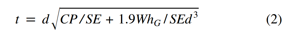
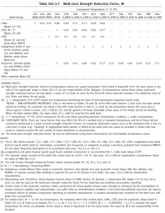
(helical seam) welded piping components, the product of the allowable stress and the applicable weld quality factor, SE, shall be multiplied by the weld joint strength reduction factor, W, when determining the required wall thickness for internal pressure in accordance with para. 304.

The designer is responsible for the application of weld joint strength reduction factors to welds other than longitudinal and spiral (helical seam) (e.g., circumferential).

The weld joint strength reduction factor, W, is equal to 1.0 when evaluating occasional loads such as wind and earthquake, or when evaluating permissible variations in accordance with para. 302.2.4. The pressure rating or allowable stress for the occasional load or variation condition is not required to be reduced by the weld joint strength reduction factor. It is also not required when calculating the allowable stress range for displacement stresses, SA, in para. 302.3.5(d). The weld joint strength reduction factor only applies at weld locations. The weld joint strength reduction factor is the ratio of the nominal stress to cause failure of the weld joint to that of the base material for the same duration. Except as provided in (f) below, the weld joint strength reduction factor, W, shall be in accordance with Table 302.3.5


More details will follow soon, keep visiting


X-Grade Pipe with A105/A234 B16.9/B16.34 Fittings

Generally A105 and 234 can be welded to X42. Over that you should spec WPH Y Grades matching your pipe. Such as X52 to WPH Y52, X60 to WPH Y60, etc.

Source: Pipelines, Piping and Fluid Mechanics engineering – Eng-Tips