flange thickness calculation can be done by different methods like :
A. If you intend to use standard flanges, and by knowing the design conditions (pressure and temp.) of piping system and type of piping material:
In this case no calculations are required to find the flange dimensions, only go to ASME B16.5 and select the rating of flanges (like as 150#, 300#, … etc.) to suit the design conditions. Just by finding the flange rating (class), you can find all standard dimensions from tables of ASME B16.5, B16.47 or MSS SP44.
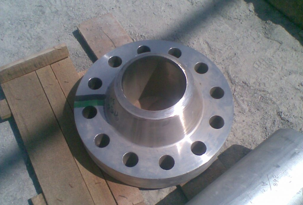
B. If you intend to use nonstandard flanges, As per ASME B31.3 Section 304.5.2 , These may be different shape. End blind.
The minimum thickness, considering the manufacturer ’s minus tolerance, shall be not less than tm
![]()
To calculate t, the rules of Section VIII, Division 1, UG-34 may be used
The minimum required thickness of flat unstayed circular heads, covers and blind flanges attached by bolts causing an edge moment in which case the thickness shall be calculated by the following formula:
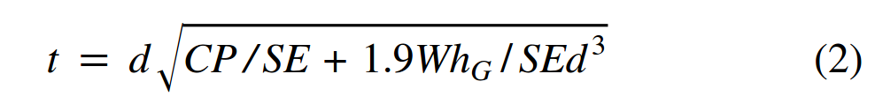
When using Formula (2), the thickness t shall be calculated for both operating conditions and gasketseating, and the greater of the two values shall be used.
For operating conditions, the value of P shall be the design pressure, and the values of S at the design temperature and W from Formula (3) of 2-5(e) shall be used. For gasket seating, P equals zero, and the values of S at atmospheric temperature and W from Formula (4) of 2- 5(e) shall be used.
Where,
C = a factor depending upon the method of attachment of head, shell dimensions, and other items as listed in (d) below, dimensionless. The factors for welded covers also include a factor of 0.667which effectively increases the allowable stress for such constructions to 1.5S. (in our case C= 0.3)
d = diameter, or short span, measured as indicated in Fig. UG-34.
E = joint efficiency, from Table UW-12, of any Category A weld as defined in UW-3(a)(1).
hG = gasket moment arm, equal to the radial distance from the center line of the bolts to the line of the gasket reaction, as shown in Table 2-5.2.
P = internal design pressure (see UG-21).
S = maximum allowable stress value in tension from applicable table of stress values referenced by UG-23.
W = total bolt load given for circular heads for Formulas (3) and (4), 2-5(e) in UG-34 of ASME BPVC VIII Dev.1.