Flange Thickness Calculation
flange thickness calculation can be done by different methods like :
A. If you intend to use standard flanges, and by knowing the design conditions (pressure and temp.) of piping system and type of piping material:
In this case no calculations are required to find the flange dimensions, only go to ASME B16.5 and select the rating of flanges (like as 150#, 300#, … etc.) to suit the design conditions. Just by finding the flange rating (class), you can find all standard dimensions from tables of ASME B16.5, B16.47 or MSS SP44.
B. If you intend to use nonstandard flanges, As per ASME B31.3 Section 304.5.2 , These may be different shape. End blind.
The minimum thickness, considering the manufacturer ’s minus tolerance, shall be not less than tm
![]()
To calculate t, the rules of Section VIII, Division 1, UG-34 may be used
The minimum required thickness of flat unstayed circular heads, covers and blind flanges attached by bolts causing an edge moment in which case the thickness shall be calculated by the following formula:
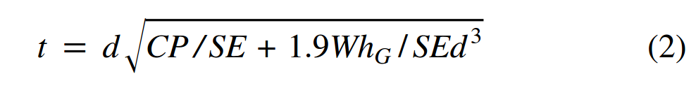
When using Formula (2), the thickness t shall be calculated for both operating conditions and gasketseating, and the greater of the two values shall be used.
For operating conditions, the value of P shall be the design pressure, and the values of S at the design temperature and W from Formula (3) of 2-5(e) shall be used. For gasket seating, P equals zero, and the values of S at atmospheric temperature and W from Formula (4) of 2- 5(e) shall be used.
Where,
C = a factor depending upon the method of attachment of head, shell dimensions, and other items as listed in (d) below, dimensionless. The factors for welded covers also include a factor of 0.667which effectively increases the allowable stress for such constructions to 1.5S. (in our case C= 0.3)
d = diameter, or short span, measured as indicated in Fig. UG-34.
E = joint efficiency, from Table UW-12, of any Category A weld as defined in UW-3(a)(1).
hG = gasket moment arm, equal to the radial distance from the center line of the bolts to the line of the gasket reaction, as shown in Table 2-5.2.
P = internal design pressure (see UG-21).
S = maximum allowable stress value in tension from applicable table of stress values referenced by UG-23.
W = total bolt load given for circular heads for Formulas (3) and (4), 2-5(e) in UG-34 of ASME BPVC VIII Dev.1.
thanks what about the valve end flange, where valve ends are open . is the same blind flange formula applies
I am looking how to calculate blind flange
You can refer ASME B31.3 Clause 304.5.2,
However Blind flanges are standard items and their thickness are given in ASME B16.5/B16.47
if you are looking for permanent blank then refer ASME B31.3 Clause 304.5.3
I have a circular diameter of 850mm and 3mm thick plate. How to calculate flange for it.
this article tells thickness calculation as per ASME B31.3. which can be checked as per ASME B31.3 Section 304.5.2.
you have selected the thickness of the plate. your query is not clear ? do you want to confirm if selected thickness (3mm ) is correct?
Hi Sudhir,
Thanks for putting up this information but it doesn’t mention the important parameter (Units of measurements).
Thanks
Vishwanath
I have a situation where I wish to re-use corroded 150# flanges that have become corroded. The plan is to skin the corroded surface off whilst leaving adequate thickness to be operationally acceptable. This is a low pressure, low temperature environment.
What is the best formula to use in this situation ?
Thank you for the information. Where Can I get table 2-5.2
I looking to machining Double studded Flange (DSA) 4 1/16 5000 psi x 4 1/16 10000 psi using the 4130 AISI raw material according to API spec 6A.
The thickness for each side is mentioned in the API stander ; please let me know who to calculate the total thickness for DSA .
thanks
its very use full site
Please tell us how to calc W by giving an example